These standard products are simple welded bellows without fittings.
They can be used when fittings are welded by the user, or customer-supplied fittings are welded by us.
* For delivery time and price,feel free to ask us using the standard product estimate request form.
* Cautions about drawings
There are two drawing types: corrugated end fittings and Y-type end fittings. Note that the drawings of corrugated end fittings show dimensions including end fittings. Bellows lengths can be changed as desired according to specifications for use.
IRIE KOKEN’s standard welded bellows are made of two types of materials: SUS316L, which is commonly used for bellows, and AM350 equivalent, which is often used for high-performance welded bellows.
Select material according to your usage environment.
How to select standard bellows
In terms of material, SUS316L is lower in unit price, but the bellows performance is superior to that of AM350; therefore, materials that enable lower-priced design vary with specification conditions.
Please feel free to inquire from here.
| Pressure conditions | (Internal) vacuum (External) atmospheric pressure |
|---|---|
| Temperature conditions | Ordinary temperature (baking temp. max. 250°C) |
| Leak rate | 1×10⁻⁹ Pa・m3/s or less |
| Bellows material | SUS316L・AM350 equivalent |
| Repetition life | 10,000, 100,000, or 1,000,000 repetitions(For AM350 equivalent, 10,000 repetitions are not available.) |
10,000 repetition life series
CAD drawing download (member registration required)
| Model | Inner diameter |
Outer diameter |
Specifications per 10mm displacement |
Effective area (cm2) |
1-block maximum allowable displacement (mm) |
Product drawing download (*) |
|||
|---|---|---|---|---|---|---|---|---|---|
| Free length |
Operating range |
Axial direction spring constant (N/mm) |
|||||||
| Lmin | Lmax | ||||||||
| NS122-1 | 8 | 22 | 15 | 7 | 17 | 3.29 | 1.77 | 40 | Corrugated or noncorrugated: Y-type: |
| NS130-1 | 17 | 30 | 13 | 6 | 16 | 5.82 | 4.34 | 60 | |
| NS136-1 | 22 | 36 | 12 | 5 | 15 | 5.57 | 6.61 | 80 | |
| NS151-1 | 36 | 51 | 10 | 4 | 14 | 7.13 | 14.9 | 120 | |
| NS170-1 | 50 | 70 | 9 | 4 | 14 | 10.41 | 28.3 | 150 | |
| NS190-1 | 60 | 90 | 9 | 4 | 14 | 11.07 | 44.2 | 130 | |
| NS194-1 | 70 | 94 | 10 | 5 | 15 | 12.80 | 52.8 | 140 | |
| NS1109-1 | 79 | 109 | 10 | 5 | 15 | 31.53 | 69.4 | 160 | |
| NS1120-1 | 90 | 120 | 10 | 5 | 15 | 27.75 | 86.6 | 170 | |
| NS1150A-1 | 100 | 150 | 10 | 5 | 15 | 31.21 | 122.7 | 170 | |
| NS1150B-1 | 120 | 150 | 10 | 5 | 15 | 23.50 | 143.1 | 190 | |
| NS1210-1 | 160 | 210 | 10 | 5 | 15 | 39.57 | 268.8 | 210 | |
| NS1270-1 | 206 | 270 | 9 | 4 | 14 | 30.20 | 444.9 | 150 | |
| NS1320-1 | 260 | 320 | 9 | 4 | 14 | 41.94 | 660.5 | 190 | |
(Unit:mm)
* For drawings, right click and click the “Save File” button.
100,000 repetition life series
CAD drawing download (member registration required)
| Model | Inner diameter |
Outer diameter |
Specifications per 10mm displacement |
Effective area (cm2) |
1-block maximum allowable displacement (mm) |
Product drawing download(*) |
|||
|---|---|---|---|---|---|---|---|---|---|
| Free length |
Operating range |
Axial direction spring constant (N/mm) |
|||||||
| Lmin | Lmax | ||||||||
| NS1022-1 | 8 | 22 | 23 | 15 | 25 | 2.14 | 1.77 | 20 | Corrugated or noncorrugated: Y-type: |
| NS1030-1 | 17 | 30 | 19 | 11 | 21 | 4.07 | 4.34 | 40 | |
| NS1036-1 | 22 | 36 | 18 | 10 | 20 | 3.72 | 6.61 | 50 | |
| NS1051-1 | 36 | 51 | 15 | 8 | 18 | 4.75 | 14.9 | 80 | |
| NS1070-1 | 50 | 70 | 15 | 7 | 17 | 6.62 | 28.3 | 100 | |
| NS1090-1 | 60 | 90 | 13 | 6 | 16 | 7.38 | 44.2 | 100 | |
| NS1094-1 | 70 | 94 | 11 | 6 | 16 | 11.38 | 52.8 | 130 | |
| NS10109-1 | 79 | 109 | 13 | 7 | 17 | 23.65 | 69.4 | 130 | |
| NS10120-1 | 90 | 120 | 13 | 7 | 17 | 20.81 | 86.6 | 140 | |
| NS10150A-1 | 100 | 150 | 15 | 8 | 18 | 20.81 | 122.7 | 130 | |
| NS10150B-1 | 120 | 150 | 13 | 7 | 17 | 17.63 | 143.1 | 160 | |
| NS10210-1 | 160 | 210 | 13 | 6 | 16 | 31.66 | 268.8 | 140 | |
| NS10270-1 | 206 | 270 | 15 | 7 | 17 | 18.12 | 444.9 | 110 | |
| NS10320-1 | 260 | 320 | 14 | 7 | 17 | 25.16 | 660.5 | 140 | |
(Unit:mm)
* For drawings, right click and click the “Save File” button.
1,000,000 repetition life series
CAD drawing download (member registration required)
| Model | Inner diameter |
Outer diameter |
Specifications per 10mm displacement |
Effective area (cm2) |
1-block maximum allowable displacement (mm) |
Product drawing download (*) |
|||
|---|---|---|---|---|---|---|---|---|---|
| Free length |
Operating range |
Axial direction spring constant (N/mm) |
|||||||
| Lmin | Lmax | ||||||||
| NS10022-1 | 8 | 22 | 31 | 24 | 34 | 1.54 | 1.77 | 20 | Corrugated or noncorrugated: Y-type: |
| NS10030-1 | 17 | 30 | 25 | 18 | 28 | 3.02 | 4.34 | 30 | |
| NS10036-1 | 22 | 36 | 24 | 16 | 26 | 2.79 | 6.61 | 40 | |
| NS10051-1 | 36 | 51 | 22 | 14 | 24 | 3.39 | 14.9 | 50 | |
| NS10070-1 | 50 | 70 | 21 | 14 | 24 | 4.55 | 28.3 | 70 | |
| NS10090-1 | 60 | 90 | 17 | 10 | 20 | 5.53 | 44.2 | 80 | |
| NS10094-1 | 70 | 94 | 16 | 9 | 19 | 7.88 | 52.8 | 100 | |
| NS100109-1 | 79 | 109 | 18 | 10 | 20 | 17.20 | 69.4 | 100 | |
| NS100120-1 | 90 | 120 | 16 | 9 | 19 | 16.65 | 86.6 | 120 | |
| NS100150A-1 | 100 | 150 | 20 | 13 | 23 | 15.61 | 122.7 | 100 | |
| NS100150B-1 | 120 | 150 | 18 | 10 | 20 | 12.82 | 143.1 | 120 | |
| NS100210-1 | 160 | 210 | 18 | 10 | 20 | 22.61 | 268.8 | 130 | |
| NS100270-1 | 206 | 270 | 21 | 13 | 23 | 12.94 | 444.9 | 110 | |
| NS100320-1 | 260 | 320 | 17 | 10 | 20 | 20.97 | 660.5 | 150 | |
(Unit:mm)
* For drawings, right click and click the “Save File” button.
100,000 repetition life series
CAD drawing download (member registration required)
| Model | Inner diameter |
Outer diameter |
Specifications per 10mm displacement |
Effective area (cm2) |
1-block maximum allowable displacement (mm) |
Product drawing download (*) |
|||
|---|---|---|---|---|---|---|---|---|---|
| Free length |
Operating range |
Axial direction spring constant (N/mm) |
|||||||
| Lmin | Lmax | ||||||||
| NA1022-1 | 8 | 22 | 20 | 12 | 22 | 2.47 | 1.77 | 30 | Corrugated or noncorrugated: Y-type: |
| NA1030-1 | 17 | 30 | 16 | 8 | 18 | 4.79 | 4.34 | 50 | |
| NA1036-1 | 22 | 36 | 15 | 7 | 17 | 4.05 | 6.61 | 60 | |
| NA1051-1 | 36 | 51 | 13 | 6 | 16 | 5.97 | 14.9 | 90 | |
| NA1070-1 | 50 | 70 | 13 | 6 | 16 | 6.19 | 28.3 | 100 | |
| NA1090-1 | 60 | 90 | 11 | 5 | 15 | 7.40 | 44.2 | 110 | |
| NA1094-1 | 70 | 94 | 10 | 5 | 15 | 12.74 | 52.8 | 140 | |
| NA10109-1 | 79 | 109 | 11 | 6 | 16 | 27.02 | 69.4 | 150 | |
| NA10120-1 | 90 | 120 | 11 | 6 | 16 | 21.87 | 86.6 | 160 | |
| NA10150A-1 | 100 | 150 | 13 | 6 | 16 | 24.97 | 122.7 | 150 | |
| NA10150B-1 | 120 | 150 | 11 | 6 | 16 | 21.25 | 143.1 | 170 | |
| NA10210-1 | 160 | 210 | 10 | 5 | 15 | 39.57 | 268.8 | 210 | |
| NA10270-1 | 206 | 270 | 12 | 5 | 15 | 23.90 | 444.9 | 80 | |
| NA10320-1 | 260 | 320 | 11 | 5 | 15 | 33.19 | 660.5 | 100 | |
(Unit:mm)
* For drawings, right click and click the “Save File” button.
1,000,000 repetition life series
CAD drawing download (member registration required)
| Model | Inner diameter |
Outer diameter |
Specifications per 10mm displacement |
Effective area (cm2) |
1-block maximum allowable displacement (mm) |
Product drawing download (*) |
|||
|---|---|---|---|---|---|---|---|---|---|
| Free length |
Operating range |
Axial direction spring constant (N/mm) |
|||||||
| Lmin | Lmax | ||||||||
| NA10022-1 | 8 | 22 | 22 | 14 | 24 | 2.24 | 1.77 | 20 | Corrugated or noncorrugated: Y-type: |
| NA10030-1 | 17 | 30 | 18 | 10 | 20 | 4.29 | 4.34 | 50 | |
| NA10036-1 | 22 | 36 | 17 | 9 | 19 | 3.57 | 6.61 | 60 | |
| NA10051-1 | 36 | 51 | 14 | 7 | 17 | 5.54 | 14.9 | 90 | |
| NA10070-1 | 50 | 70 | 15 | 7 | 17 | 5.63 | 28.3 | 90 | |
| NA10090-1 | 60 | 90 | 13 | 6 | 16 | 6.58 | 44.2 | 100 | |
| NA10094-1 | 70 | 94 | 11 | 6 | 16 | 11.32 | 52.8 | 130 | |
| NA100109-1 | 79 | 109 | 11 | 6 | 16 | 27.02 | 69.4 | 150 | |
| NA100120-1 | 90 | 120 | 11 | 6 | 16 | 21.87 | 86.6 | 160 | |
| NA100150A-1 | 100 | 150 | 13 | 6 | 16 | 24.97 | 122.7 | 150 | |
| NA100150B-1 | 120 | 150 | 13 | 7 | 17 | 18.60 | 143.1 | 160 | |
| NA100210-1 | 160 | 210 | 13 | 6 | 16 | 31.66 | 268.8 | 140 | |
| NA100270-1 | 206 | 270 | 15 | 7 | 17 | 19.12 | 444.9 | 120 | |
| NA100320-1 | 260 | 320 | 14 | 7 | 17 | 26.55 | 660.5 | 140 | |
(Unit:mm)
* For drawings, right click and click the “Save File” button.
Welding grooves for fittings are also important dimensions that affect the performance of bellows.
When using our bellows, process fittings to the following dimensions.
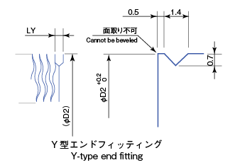
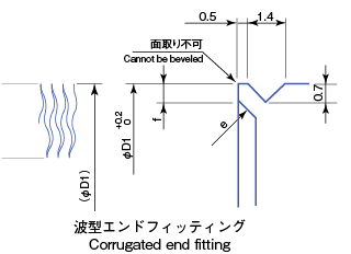
| Bellows size | Y-type end fitting | Wave-shaped end fitting | ||||||
|---|---|---|---|---|---|---|---|---|
| Fitting length | D | A | Fitting length | D | A | e | f | |
| 8×22 | 3 | 21.9 | 0.2 | 1.5 | 21.8 | 0.2 | C1.0 | 0.8 |
| 17×30 | 3 | 30.1 | 0.2 | 1.5 | 30.1 | 0.2 | C1.0 | 0.6 |
| 22×36 | 3 | 35.9 | 0.2 | 1.5 | 36.0 | 0.2 | C1.0 | 0.8 |
| 36×51 | 3 | 50.9 | 0.2 | 1.5 | 51.0 | 0.2 | C1.0 | 0.8 |
| 50×70 | 3 | 69.4 | 0.2 | 1.5 | 69.6 | 0.2 | C1.0 | 1.0 |
| 60×90 | 4 | 89.4 | 0.2 | - | 89.5 | 0.2 | C1.0 | 1.3 |
| 70×94 | 4 | 94.0 | 0.2 | - | 93.9 | 0.2 | C1.0 | 1.2 |
| 79×109 | 4 | 108.9 | 0.2 | - | 108.9 | 0.2 | C1.5 | 1.7 |
| 90×120 | 4 | 120.2 | 0.2 | - | 119.5 | 0.2 | C1.0 | 1.1 |
| 100×150 | 4 | 149.3 | 0.2 | - | 149.4 | 0.3 | C1.0 | 1.8 |
| 120×150 | 4 | 150.2 | 0.2 | - | 149.7 | 0.2 | C1.0 | 2.1 |
| 160×210 | 5 | 209.2 | 0.2 | - | 208.1 | 0.3 | C3.0 | 2.8 |
| 206×270 | 5 | 270.4 | 0.2 | - | 270.0 | 0.3 | C3.0 | 2.0 |
| 260×320 | 5 | 320.3 | 0.2 | - | 318.9 | 0.3 | C3.0 | 2.8 |
* The plate thickness of Y-type end fittings is 0.4mm.
(Unit:mm)
 Vacuum valves
 Vacuum piping parts